
Safety First - Isolation Procedure
Before touching any street light: isolate the circuit at the MCB panel - not just the local switch. Verify isolation with a non-contact voltage tester at the luminaire junction box. Place safety cones around the base of the pole. Use a fibreglass ladder - never aluminium on electrical work. Wear rubber-soled footwear and insulated gloves. If the pole is above 6m, use a proper elevated work platform (EWP/bucket truck) - do not use a ladder for heights above 6m for electrical work. Never work on a live circuit. Never assume the MCB is off just because someone said so - verify with a tester.
Diagnosing What Failed
Before climbing: observe the symptom. Light completely dead: could be driver, LED module, fuse, or wiring. Light flickers: almost always the driver. Light stays on during day: photocell/sensor. Light very dim: driver output low, LED chips degraded, or dirty cover glass. Test from the ground: measure voltage at the junction box with a multimeter (long probe leads). If 230V is present at the junction box but the light is dead: the fault is inside the luminaire (driver or LED). If no voltage: fault is upstream (MCB, cable, connection). This diagnosis saves an unnecessary climb.
Driver Replacement - Step by Step
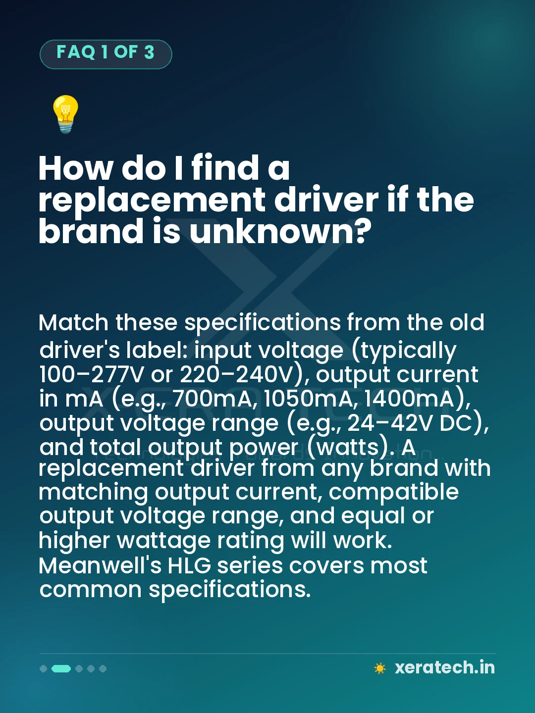
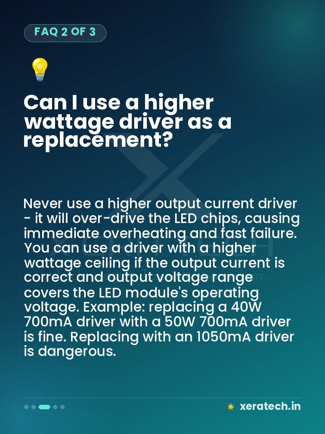
Open the luminaire: most street light fixtures have a cover secured by 4–6 hex bolts or a latch. The driver is a rectangular metallic box mounted on a bracket inside the housing. Note the driver specifications printed on its label: input voltage (should match 230V), output voltage (e.g., 36V DC), output current (e.g., 700mA). Photograph the wiring before disconnecting. Disconnect the input (AC side) first, then output (DC to LEDs). Remove mounting screws. Install new driver with identical or compatible specifications - the output current must match exactly (±5%). Reconnect output first, then input. Apply silicone sealant at the cable entry point before closing.
LED Module Replacement
LED modules in street lights are typically PCB assemblies with multiple SMD chips soldered on. To replace: photograph the wiring. Disconnect the LED connector or terminals. Remove the PCB mounting screws (typically 4–6). Slide out the PCB. The replacement module must match: same PCB dimensions, same forward voltage (check with a bench power supply or verify with the driver's output voltage), same number of LED chips or total load current. Reinstall with thermal paste between the PCB and the aluminium heat sink body - this is critical. Without thermal paste, the LED junction temperature rises 15–20°C and the new module will fail prematurely. Apply a thin, even layer of thermal compound to the back of the PCB before installing.