Pre-Installation Checklist
Verify approved lighting layout drawing (pole positions, cable route). Confirm material delivery against BOM (Bill of Materials). Check BIS marks on all LED fixtures. Test continuity of cable drums before laying. Confirm earthing material is available (GI wire, earth electrode, bentonite). Ensure all required permits are in place (road-cutting permission, traffic diversion plan if applicable). Brief the installation crew on safety - PPE mandatory for all pole work.
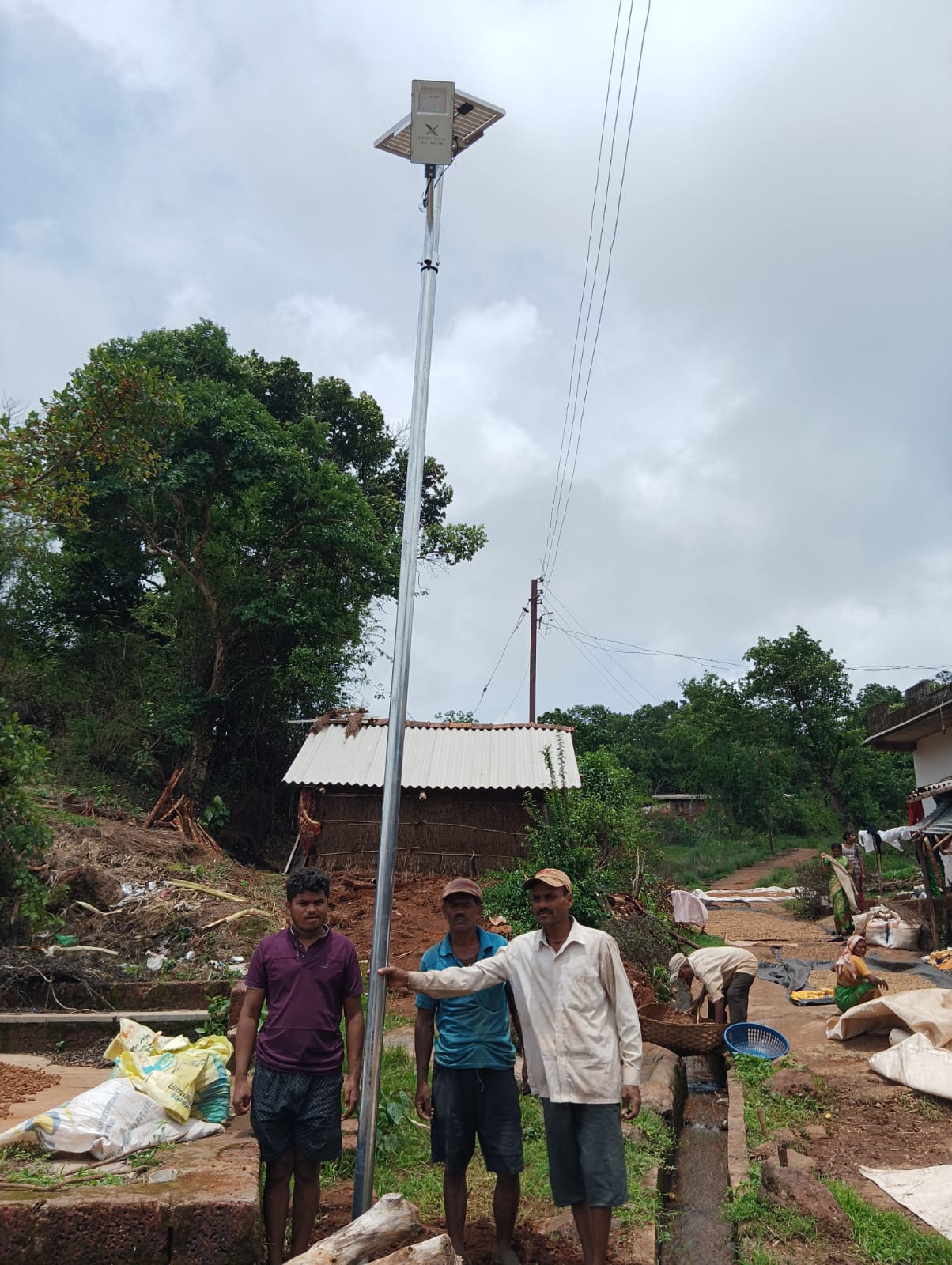
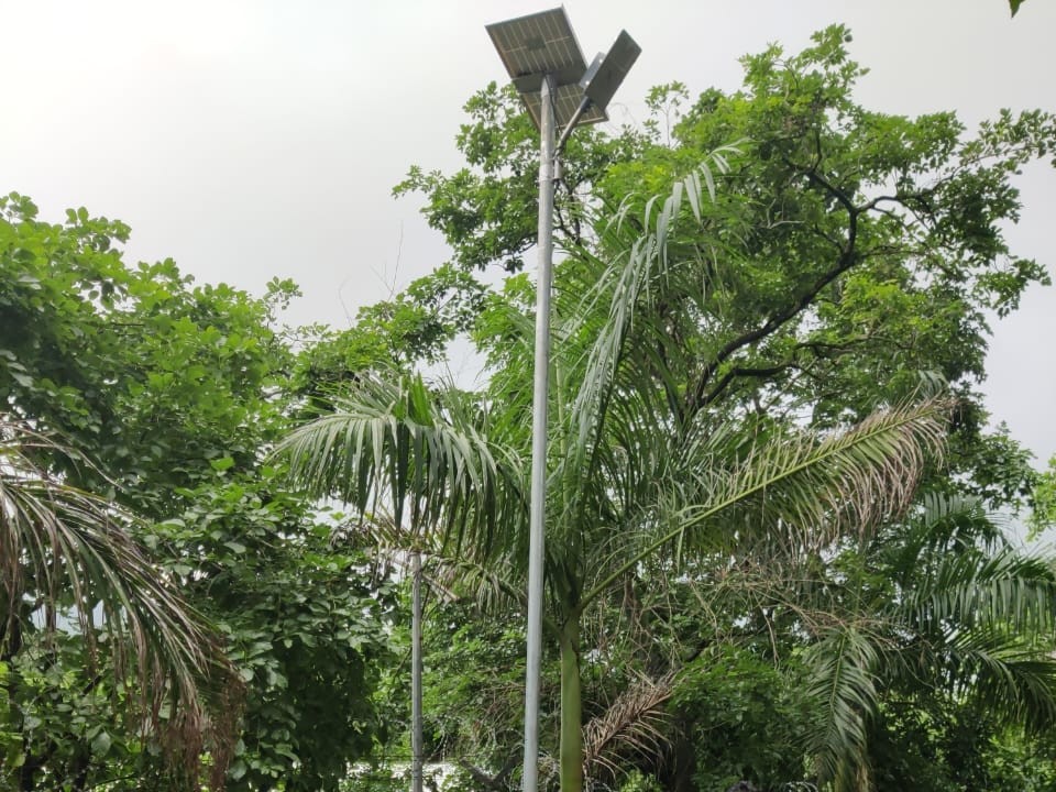
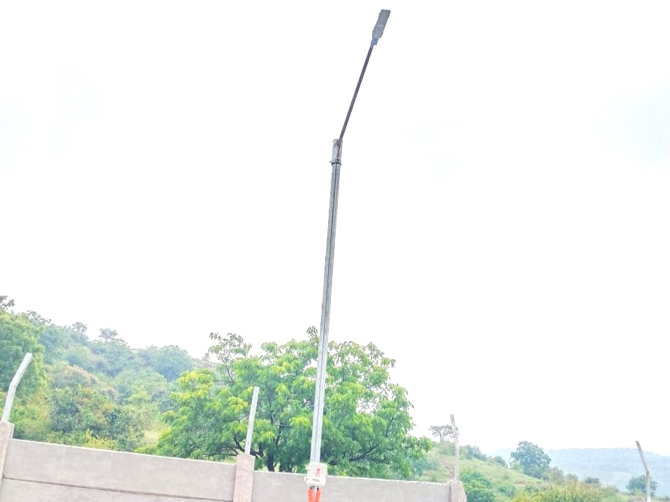
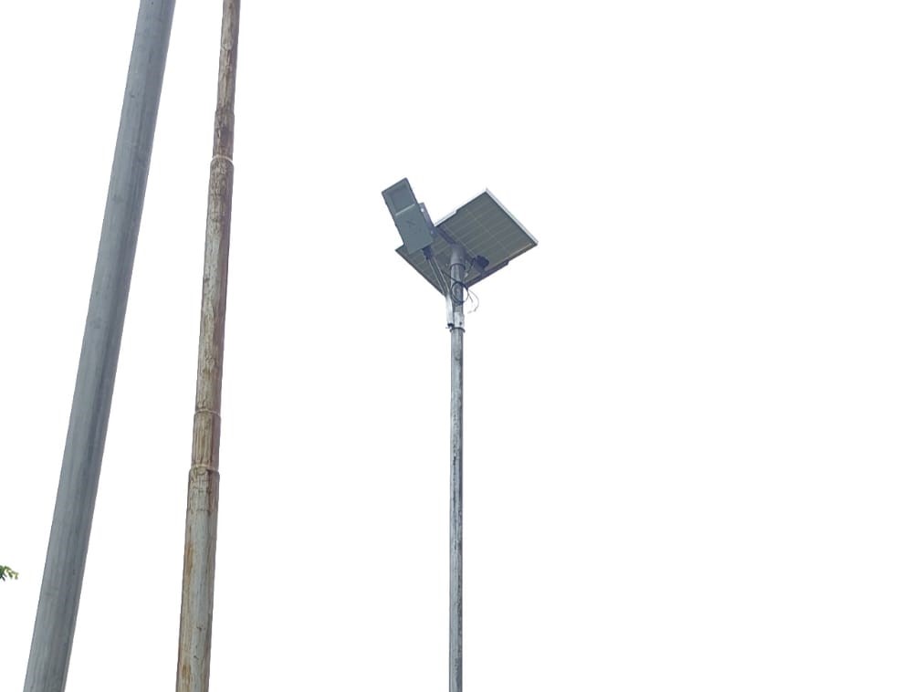
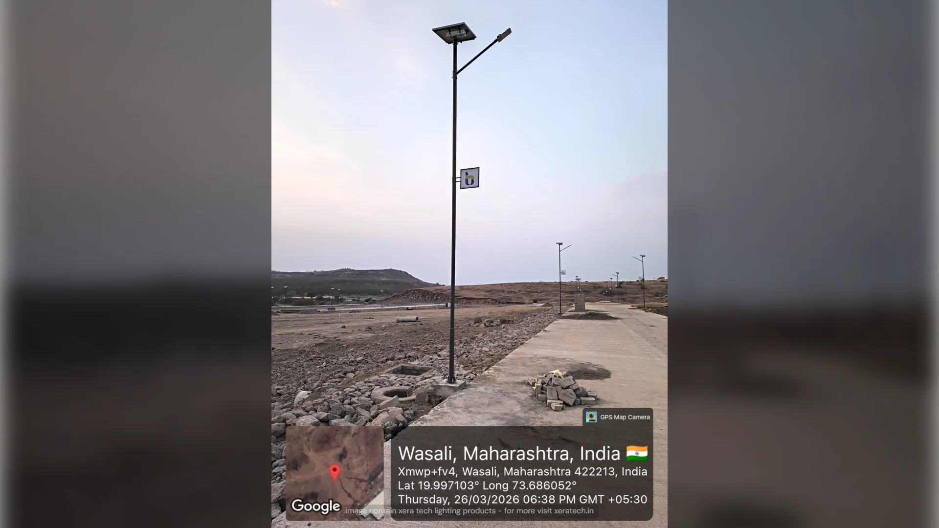
Pole Foundation and Erection
Excavate pole pits as per drawing (depth = pole height ÷ 6, minimum 900mm for 5m poles). Set GI base plate and anchor bolts. Concrete mix M15 (1:2:4) poured and tamped. Cure minimum 48 hours before loading. Erect pole with crane or manual A-frame. Verify plumb with spirit level - tolerance ±2mm per metre of height. Torque anchor bolts to specification (typically 50–80 Nm for M16 bolts). Apply anti-corrosion compound on all exposed threads.
Cable Laying and Conduit
Cable route: lay 4-core armoured cable (AYWY type for underground, TW type for overhead) as per drawing. Depth for underground: minimum 600mm for LT cables under roads, 450mm under footpaths. Lay sand bedding (75mm) below cable and cover with sand+bricks above for protection. For conduit runs inside the pole: use 25mm GI conduit, properly earthed. Cable entry at pole base: use double compression cable glands, IP65 rated. Label all cables at both ends.
Earthing System
Each pole requires a dedicated earth electrode. Minimum: 2.5m × 16mm GI earth pipe driven vertically, connected to a 8 SWG GI earth wire running in the cable trench to a system earth pit. Earth resistance per pole: maximum 5 ohms as per IS 3043. Test with an earth megger and record values in the commissioning report. Connect the luminaire housing, pole body, and cable armour to the earth conductor. Use proper mechanical clamps - never rely on screws alone for earth continuity.
Commissioning and Handover
After completing installation: test insulation resistance (IR) of all cables - minimum 1 MΩ at 500V Megger. Check loop impedance and verify MCB trip characteristics. Energise the panel and measure voltage at each pole terminal (maximum 2% drop from supply point). Measure lux at ground level and compare with design values. Fill in the commissioning report including: pole numbers, GPS coordinates, cable lengths, IR test values, earth resistance values, and lux readings. Handover includes: as-built drawings, test certificates, warranty cards, and operation manual.